
Movement Mapping (MM)
J Jerosch and M Schneppenheim of the Orthopaedic Surgery Department, Johanna-Etienne-Hospital, Neuss, Germany, and A Weipert and St Hanusek of Orthopaedic Services (Mainhausen), describe dynamic, pre-operative surgical planning for total hip replacement
During the past decade total hip replacements have increased, even for younger patients with degenerative joint disease. Due to new bearing surfaces, such as the ceramics-ceramics combination, the range of postoperative free movements is gaining importance, particularly for younger patients.
With ceramics bearing surfaces, the load edge needs special attention, so more precise implantation is necessary. Apart from infection, dislocation represents one of the main postoperative complications, resulting in delayed mobilisation, extended rehabilitation time or, if recurring, even revision surgery, which causes significant stress for patient/doctor. In recent studies, joint instability is show to occur in 1.5-4% of all first hip replacements and revision surgery can increase up to 26%, which may have considerable socio-economic and psychological consequences.
Apart from implant positioning, the geometry of the prosthesis is decisive for a free range of movements. Thus, the prosthesis head size is as crucial for the development of a luxation as is the relation of the head to its neck. The bigger the head, the greater the freedom of joint movement, without which the prosthesis neck will make contact with the acetabular edge, whereas smaller head designs tend towards dislocation due to an implant-implant impingement.
The purpose of our study was to describe the influence of implant positioning on the available movement range (implant impingement).
Via computer simulation, the movement range (Movement Mapping = MM) of a hip joint after conventional endoprosthesis was described. Only head length (length M) and diameter (28mm) were constant measurements in this analysis. All other geometrical parameters were variable.
A range from 35º to 55º was simulated for the inclination of the acetabulum. The acetabular anteversion was simulated from -10º to +20º. At the shaft, the CCD angle was simulated between 115º and 145º and the anteversion between -5º to +45º.
The possible movement range of the thigh was analysed as follows:
• flexion: 0º - 110º
• internal/external rotation: 60º - 0º - 60º
• abduction/adduction: 60º - 0º - 60º.
The calculation is a sequential impact observation, in relation to a corresponding range of interest (ROI). This is derived from intra-operative data and from the patient’s physical movement range.
The computer programme was based on Borland C++. The basis for processing individual patient data is a non-commercial programme developed by Orthopaedic Services, through which anatomically adapted endoprosthesis are developed. The platform for the whole programme is MS-DOS, but the programme also runs as a task under Windows 95/98, ME, NT and 2000. For up-to-date application, the system needs Pentium 1. Depending on the rhythm frequency, simulation time of a data record is about five minutes at 1.2 GHz, up to 4 hours at 75 MHz. The system has an open data-port for processing impingement data, with customary spread sheets (EXCEL) to represent and evaluate the data.
Results
These demonstrate that a practical model could be introduced with the virtual computer simulation. The results are plausible and correspondent to clinical experience.
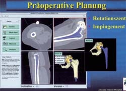
Some examples of Movement Mapping (MM)
• In a simulation with a shaft CCD angle of 115º and a shaft anteversion of -5º, the motion range with an acetabular position of -10º anteversion and 35º inclination is clearly lower (above) than with a acetabular anteversion of 20º and inclination of 55º (below).
• The free range of motion is clearly shifted with a shaft at a CCD angle of 155º and an anteversion of 45º. This is valid both for an acetabular anteversion of -10º with an inclination of 35º (above) as for an anteversion of 20º and an inclination of 55º (below).
Independent of all other parameters, the calculation of the shaft anteversion influence shows an optimal motion between 20º and 30º. Independent of all other parameters, the calculation of the influence of the CCD-angle shows an optimal motion between 120º and 130º. Independent of all other parameters, the calculation of the influence of the acetabular anteversion shows an optimal motion between 10º and 20º.
Analysis of the acetabular inclination shows a decreasing motion range with increasing inclination.
Discussion
The contact free range of motion has special clinical relevance for patients with an alloarthroplastic hip replacement. The theoretical angle freedom of movements of the endoprosthesis components in two vertical levels was stated for semi-circular acetabulum with 110º. However, these calculations only allow for limited conclusions about the complicated axis environment in situ. With fully or partially restricted mobility, it must be assumed that the implant neck strikes the acetabular edge. For several reasons, these impingement phenomena are to be regarded as a possible factor for aseptic loosening. On the one hand, the impingement happens within the artificial joint, i.e. without any ligament or muscular protection; on the other hand, the acetabulum is loaded tangentially to its sphericity. That particularly gave a biomechanically more favourable spherical acetabulum at the weakest position. Thirdly, a resulting force that also has a dimension of 300 kp with everyday load is considerably high. This problem of early aseptic loosening and implant dislocation due to prosthesis positioning has been increasingly considered in literature. Out of 95 patients with unstable hip arthroplastic, Daly and Morrey discovered that unfavourable positioning of the prosthesis components was the cause in 45 patients.
In a biomechanical study and virtual computer analysis, Gondi et al. and Seki et al. pointed to the crucial interference of acetabulum and femoral component position, as well as neck length and head diameter. To avoid such failures due to acetabular impingement and to improve the prosthesis motion range, computer-assisted intra-operative navigation systems have increasingly been evaluated. With these, a precision of 0.2 mm and 0.2º can be reached. Depending on the surgical procedure, these values are probably not realistic in everyday surgical routine. Nevertheless, clearly it can be expected that the precision of the acetabulum and shaft positioning will increase.
In terms of the high precision achievable with modern navigation systems, the question of which position to aim for, remains. The literature makes the following, general recommendations:
Tolerable values for the acetabular inclination are 40 +/- 5 degrees and for the anteversion of the acetabulum 5-25 degrees. For evaluation of the acetabulum the individual performance of patients as well as their load situation must be considered. The greater the proportion of sedentary activity, the greater the anteversion of the acetabulum that should be chosen to prevent posterior instability. The anteversion of the shaft should lie between 5 and 15º, the prosthesis head diameter being twice the size of the neck diameter. The bigger the implanted head, the lesser the risk of dislocation.
However, these recommendations only represent statistical mean values that need modification, depending on the individual patient and implant characteristics.
At this point, the introduced principle can be of major importance in the future. In terms of individual parameters, the optimal component positioning can be calculated for each patient, and these data are the basis for the intraoperative navigation systems. Only this combination makes the high precision of computer assisted implantation in hip endoprosthetics meaningful, so that the aims for navigation are determined not only from a surgeon’s experience, but via objective data.
Unlike the purely static planning systems available until now (aimed at a fitting strategy for prosthesis components), with Movement Mapping (MM), finally dynamic surgical planning is available.
Details: jerosch@jek-neuss.de
30.04.2003