
Sponsored • White paper
A new radiation survey meter for hospitals: the RaySafe 452
Ionizing radiation is not visible to the human eye. It does not smell or make a noise, and you cannot feel it. In the complex and busy environment of a hospital, how can you ensure that patients and staff are not exposed to more ionizing radiation than necessary?
Ionizing radiation is utilized for different purposes in medical procedures, with the three main areas being diagnostic imaging, nuclear medicine, and radiotherapy. While the use of ionizing radiation in healthcare saves many lives, the benefits are balanced against the fact that exposure to ionizing radiation can be harmful to the human body. Occupational groups like medical physicists and radiation safety officers work with monitoring, controlling and reducing the amount of unnecessary environmental radiation in hospitals. To lower the risks of unwanted radiation-induced effects, the goal is to minimize the exposure to unnecessary radiation, both for patients and staff. To be able to take the correct measures, it is essential to know the properties of the radiation in terms of energy range, dose rate, type of radiation, and more. This is where radiation survey meters are needed.
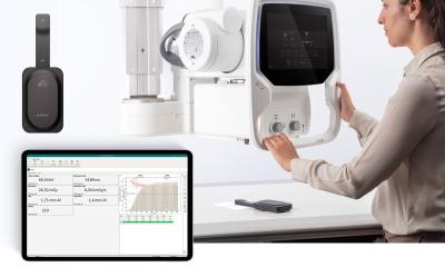
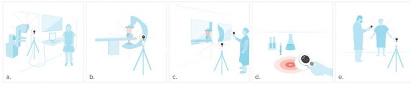
Figure 1 illustrates some measurement scenarios and demonstrate the wide range of measurement needs in hospitals. Table 1 gives an overview of the main areas of application of survey meters in hospitals, with quantities, units, and typical energy ranges of the radiation.
Radiation survey meters: Technology
How can ionizing radiation be measured, and what are the limitations? The general principle of radiation survey meters is that ionizing radiation changes the electron state of the material in the detector, in a way that can be detected and quantified. Hence, the physical properties of the meter materials in the detector bring both possibilities and limitations for radiation measurements.
Ionization chambers (ion chambers) measure the ability of radiation to ionize gas. In ion chambers, the detector is part of an electrical circuit enclosed in a gas-filled chamber (usually air). A voltage is applied across two electrodes to create an electric field. Radiation that penetrates the chamber will ionize the gas molecules and form ion pairs, consisting of an electron and a positively charged ion. The electrons will move towards the positively charged plate, while the positively charged ions will move to the negatively charged plate. This current is proportional to the amount of ionizing radiation and is therefore proportional to dose in air.
An ion chamber can be vented or sealed. Some models come with a hatch, with a thinner wall material behind, to enable beta radiation measurements. Vented air chambers have a flat energy response but require corrections for ambient temperature and pressure. Sealed ion chambers commonly have a drop in sensitivity (in air kerma) below 50-100 keV due to attenuation of the radiation in the wall of the chamber.
The sensitivity of an ion chamber increases with the chamber size since a higher number of molecules brings more ionization possibilities. Alternatively, the number of contained molecules can be increased by pressurizing the chamber. However, pressurization requires thicker chamber walls that further attenuates low energy photons, and may make the instrument classified as hazardous material (hazmat).
A Geiger-Müller tube (GM tube) also consists of a gas-filled chamber but, compared to an ion chamber, a GM tube has a higher applied voltage and a different chemical composition of the contained gas. When ionizing radiation hits the chamber, secondary electrons are produced from interactions with the wall material. Due to the large potential difference, the electrons are accelerated towards the anode and reach energies that are high enough to ionize the gas molecules in the chamber. As a result, avalanches of ionization events are created, resulting in a complete ionization of the gas around the anode on the time scale of microseconds. This discharge event corresponds to one count in a GM based instrument.
GM detectors are commonly designed as cylindrical tubes, or as pancake tubes optimized for contamination measurements. Depending on the design, the GM tube can detect α, β, and γ radiation. The high signal level of the GM tube makes it a sensitive and cheap detector. GM detectors have a strong energy dependence at low photon energies, but with filtration they can be energy compensated and used for dose rate measurements. However, since the GM tube does not measure energy but number of events (counts), no spectral information is given.
Another consideration with GM tubes is the deadtime effect: When an avalanche has started, the GM tube is insensitive to incoming radiation for some time, since the electrodes in the circuit are temporarily neutralized. During this dead-time period, no radiation is registered. At high dose rates, the dead-time and the sensitivity of the instrument may cause the GM tube to saturate.
While ion chambers and GM tubes utilize gas, semiconductor diodes are made of solid material. As the name implies, the diode is neither a conductor, nor an insulator but something in-between. Semiconductor diodes are commonly made of silicon crystal and doped with atoms that provide extra electrons to the crystal structure, e.g., phosphor. These excess electrons help to narrow the band gap from the valence band to the conduction band of the crystal. In other words, a rather small uptake of energy makes the diode material work as a conductor. As ionizing radiation hits the diode, it interacts with the crystal material and produces free electrons. The kinetic energy of these electrons, moving through the crystal structure, is enough to excite other electrons in the crystal to the conduction band and cause formation of electron-hole pairs.
Since the densities of solid materials are typically hundreds, or even a thousand times, higher than that of gases, semiconductor detectors are much smaller and more robust detectors than ion chambers and GM tubes. The higher density in combination with a narrow band gap leads to a sensitivity that is up to one million times higher than that of an ion chamber of corresponding volume. However, the high sensitivity of semiconductor diodes comes with a temperature dependence, since even a small rise in temperature may cause some electrons to pass to the conduction band. Since the sensitivity of the diode varies with photon energy, filters are often used in front of the diode to attenuate lower energies and moderate the energy response.
A scintillator is a material that emits light at interaction with radiation. Ionizing radiation excites the scintillator molecules to a higher energy state. Since this state is energetically unfavorable, the molecules quickly release their excess energy as photons (light) to relax to the ground state. This emitted light can be registered and used as a measure of the ionizing radiation. A light sensor, for instance a photo multiplier tube (PMT) or photo diode, is needed to convert the light into an electric signal.
Scintillator detector materials can be organic or inorganic, and of crystal, liquid or plastic type. Due to the large variety of scintillator detectors, a comprehensive description of their properties cannot be given here. However, some general considerations with scintillator detectors are their temperature dependence, sensitivity to humidity, and decay time of the scintillating material. A slow decay leads to afterglow in the scintillator which causes a correspondingly slow readout.
For more information about survey meters and their properties, there are excellent textbooks on the subject, for instance, Introduction to Radiological Physics and Radiation Dosimetry by F.H. Attix (Wiley, 2007).
Why a new survey meter?
Energy dependence
To give a representative description of the radiation environment, a survey meter should have a flat response at energies where the main portion of the photons are. However, all survey meters have a varying energy response in parts of its measurement range due to the individual properties and limitations of each instrument type and technology. As shown in Table 1, photon energies from radiation equipment in hospitals range from 10 keV to several MeV.
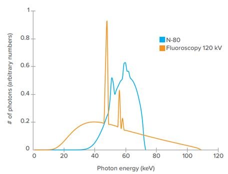
If the survey meter does not have a flat energy response, correction factors may be given in the specifications of the instrument. Using correction factors is challenging: First, energy response graphs are typically based on narrow beam spectra. In real life, ionizing radiation from X-ray machines (and medical linear accelerators) interacts with various inherent and external filtration materials before hitting the survey meter, thus the resulting photon energy spectrum is broad. A single narrow spectrum at a certain energy is therefore a poor approximation of the distribution of photon energies from an X-ray machine (Figure 2), and the corresponding correction factors may not hold.
Secondly, many instruments are calibrated at one energy only, for instance, to the photon energies of Cs-137. This radiation source is rarely used in hospitals and does not reflect the complex composition of energies in scattered radiation from X-ray machines and linacs.
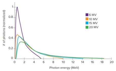
Most survey meters do not measure at energy levels as high as the maximum set energy of medical linacs. However, while medical linacs can have settings as high as 24 MV, the energy of the photons from the linac is much lower than the setting in the machine implies, and the resulting spectrum is wide. Figure 3. Another consideration with measurements on linacs is that the rate during the short pulses are extremely high, which may cause saturation of scintillators and GM tubes. Taken all together, it is a complex measurement situation and there are few survey meters that have a well-known behavior for measurements on medical linacs.
Wall leakage measurements is a common measurement situation in hospitals that typically require a meter with fast response time in combination with high sensitivity. However, survey meters are commonly unstable at low dose rates, when close to background radiation levels, and have slow response due to long integration times. With fluctuating dose rate values, it is difficult to determine whether there is an elevated level of radiation or not. If the meter response is slow, it may not react to a sudden, higher level of radiation when performing area radiation measurements
Challenging measurement cases
Measurements of scattered radiation from pulsed radiation sources, like pulsed X-ray fluoroscopy and medical linear accelerators (linacs) can be difficult. In pulsed fluoroscopy, the pulse lengths typically range from 2-20 milliseconds (ms), and the pulse repetition rate is 1-30 Hz. For medical linacs, pulses are only a couple of microseconds (µs) long and have a high pulse repetition rate, about 100 Hz.
Most survey meters do not measure at energy levels as high as the maximum set energy of medical linacs. However, while medical linacs can have settings as high as 24 MV, the energy of the photons from the linac is much lower than the setting in the machine implies, and the resulting spectrum is wide. Figure 3. Another consideration with measurements on linacs is that the rate during the short pulses are extremely high, which may cause saturation of scintillators and GM tubes. Taken all together, it is a complex measurement situation and there are few survey meters that have a well-known behavior for measurements on medical linacs.
Wall leakage measurements is a common measurement situation in hospitals that typically require a meter with fast response time in combination with high sensitivity. However, survey meters are commonly unstable at low dose rates, when close to background radiation levels, and have slow response due to long integration times. With fluctuating dose rate values, it is difficult to determine whether there is an elevated level of radiation or not. If the meter response is slow, it may not react to a sudden, higher level of radiation when performing area radiation measurements
Practical considerations
To cover the wide range of measurement needs listed in Table 1, radiation safety staff typically need to use multiple instruments based on different technologies. This situation does not only result in a lot of instruments to carry around but also many instruments (and software) to buy, learn, teach, maintain, calibrate, repair and store.
Ion chambers are often considered as the gold standard technology for survey measurements due to their flat response, wide energy range and high sensitivity. However, to have a flat energy response over a wide range of energies, the ion chamber needs to be vented and have a large volume. Such a meter is fragile and requires correction for pressure and temperature. Sealed ion chambers are less fragile and can also be pressurized. While pressurization of the chamber increases the sensitivity of the meter, it requires thicker chamber walls, attenuating low energy photons. Furthermore, with pressurization comes the drawback of the survey meter being classified as hazardous material (hazmat), which brings restrictions for travels by air and shipping. Even if the user does not need to travel, the meter may still need to be shipped for calibration and service.
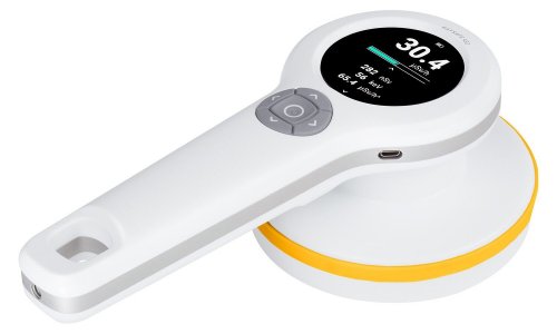
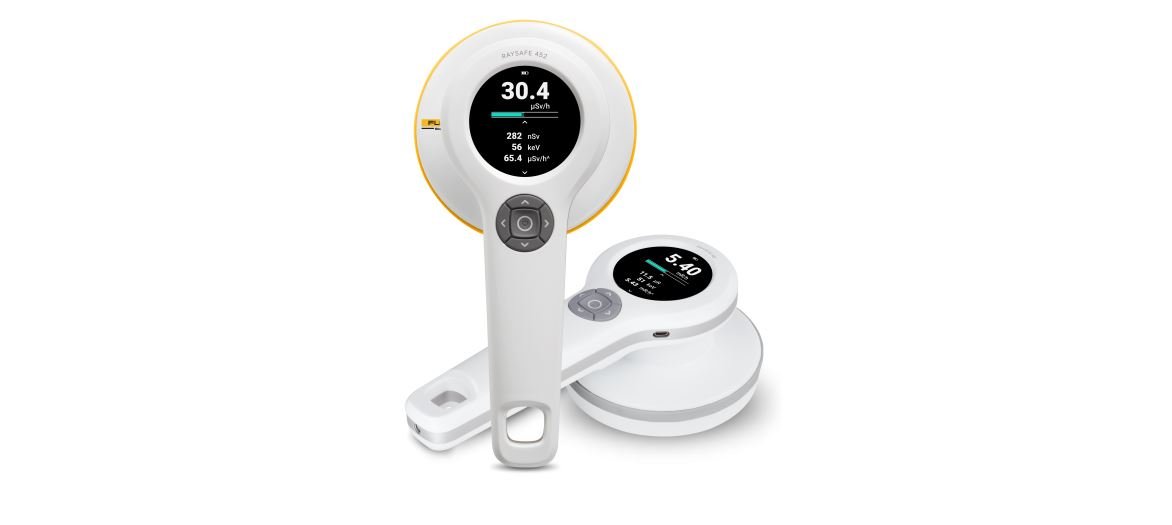
The RaySafe 452
Design and general features
Traditionally, the technology inside a survey meter determines the area of application: Ion chambers are normally used for leakage and scatter measurements, while GM tubes are used for detection of spilled isotopes and other contamination. The RaySafe 452 takes a different approach and seamlessly combines several measurement technologies in one instrument: Semiconductor diodes, scintillators, and a GM pancake. The RaySafe 452 handles simultaneous measurements of different types of radiation, as well as different energies, and follows the requirements for additivity according to IEC 60846-1.
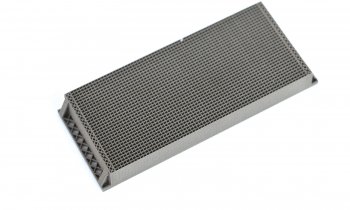
Figure 4 gives an overview of the RaySafe 452 and what it measures. The active sensor area consists of a GM pancake behind a steel grid, surrounded by a cluster of solid-state sensors behind a carbon fiber cover. In addition, the RaySafe 452 comes with two interchangeable lids— Ambient and Air kerma1. With any lid mounted, the RaySafe 452 measures dose and dose rate. Without a lid mounted, the RaySafe 452 measures counts of α, β and γ radiation.
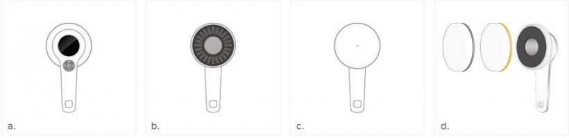
Dose and dose rate
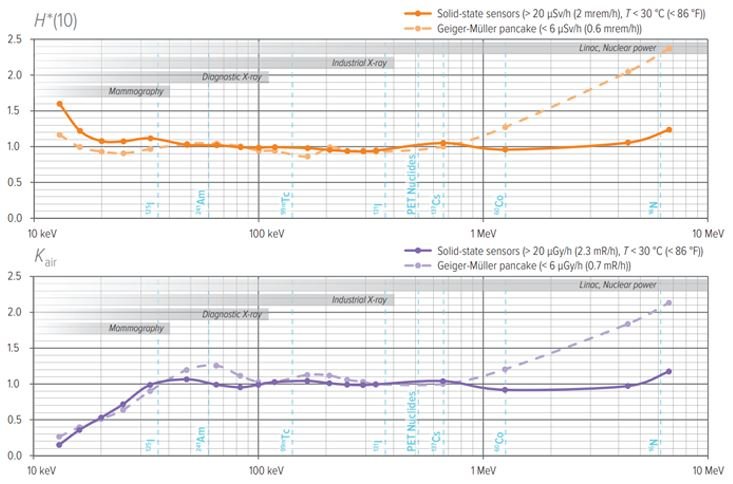
The interchangeable lids alter the filter composition in front of the GM tube and switches the energy response of the solid-state sensors. With a lid mounted, the active sensor area corresponds to the size of the flat part of the lid (Figure 4c). With the yellow lid mounted, the RaySafe 452 measures ambient dose equivalent (H* (10)), and with the gray lid mounted it measures air kerma (Kair). Each model has several different filtration combinations, where each combination covers a specific energy range and constitutes a separate channel in the meter. The different filter combinations are used to attenuate or boost certain photon energies and are designed to give a flat energy response over a wide range of energies, Figure 5. For dose and dose rate measurements, the RaySafe 452 utilizes information from both the GM pancake and the cluster of solid-state sensors.
Since both systems measure continuously, and have a flat energy response, data from the two can be used in the same measurement. Data from the GM pancake is used at low rates, and data from the solid-state sensors are used at high rates (Figure 6). For intermediate rates, the meter automatically selects what data to use, depending on what is more suitable at the current rate level and ambient temperature. As discussed earlier, a discharge event in a GM pancake typically takes place on the microsecond (µs) time scale and causes some dead-time in the meter. To compensate for these periods of insensitivity, the RaySafe 452 performs dead-time corrections each millisecond (ms).
Mean photon energy
The RaySafe 452 measures mean photon energy according to the definition in ISO 4037-1:2019. Mean photon energy is calculated from the signals from the different channels of the solid-state sensors. Since each separate channel has a wellknown energy response, the energy distribution of the radiation that hits the meter can be derived from the signal. The GM tube is not used for mean photon energy measurements, since it does not give spectral information.
Pulsed exposures
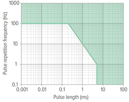
The RaySafe 452 handles short pulse lengths and high pulse repetition frequencies and is designed to measure on pulsed fluoroscopy as well as medical linacs, Figure 6. When measuring dose rate on pulsed exposure, the RaySafe 452 displays the average dose rate. Dose rate is averaged over at least one second and updated once per second. Therefore, the radiation pulse needs to be longer than two seconds for the instrument to show the rate during a pulse. However, if the pulse length is known, the rate per pulse can be calculated for shorter pulses, since dose measurements are accurate for much shorter pulse lengths, as demonstrated in Figure 6.
Response time
The speed of a survey meter can be described in different ways. The start-up time of the RaySafe 452 is 5 seconds. The typical response time of the meter is about 2 seconds but varies slightly with dose rate. The time to maximum stability ranges from two seconds, for high dose rates, to 60 seconds for dose rates at background level2, thus the RaySafe 452 is compliant with the requirements for response times as defined in IEC 60846-1:2009.
Counts Without a lid mounted, only the GM pancake is in use and the active sensor area corresponds to the gray area in Figure 4b. In this mode, the RaySafe 452 counts α, β and γ radiation3 and can be used for contamination measurements. The RaySafe 452 does not identify nuclides but the approximate activity of a known nuclide can still be calculated from the measured count rate. A table of conversion factors from count rate to activity for common nuclides is found in the user manual.
Measurement examples
To demonstrate the versatility of the RaySafe 452, we use the measurement cases in Figure 1 as an example:
- To measure tube leakage in Gy (or rad or R), mount the Air kerma lid and position the RaySafe 452 at suitable distance from the focal spot. The handle of the RaySafe 452 has a tripod screw mount.
- To measure scattered radiation, switch to the Ambient lid. The RaySafe 452 automatically changes units to Sv (or rem) and no settings are required.
- To measure wall leakage, slowly sweep the instrument across the areas of interest. No gain settings are needed.
- To measure contamination, unmount the lid and slowly scan the area of interest, using the sensor area of the GM pancake. The RaySafe 452 automatically changes units to counts (cps or cpm).
- To check the amount of radiation from a patient that have had an intake of radioactive drugs, mount the Ambient lid to measure dose rate in Sv (or rem). Unmount the lid to measure counts in cps (or cpm).
All measurements are automatically stored in the instrument and can be transferred to a computer via RaySafe View (software).
The RaySafe 452 addresses the identified issues discussed in this article. To summarize, the survey meter:
- Has a flat energy response and does not require correction factors.
- Has a well-known behavior for short pulse lengths and high pulse repetition rates, which enables measurements on pulsed X-ray fluoroscopy and medical linear accelerators.
- Measures background radiation and is suitable for wall leakage measurements.
- Is not pressurized and not classified hazardous material (hazmat).
- Is designed to cover the survey meter measurement needs in diagnostic imaging, nuclear medicine and radiotherapy, in one single instrument.
- Automatically stores all measured data in the instrument.
For more information about the RaySafe 452, visit flukebiomedical.com/452.
- There are three different models of the RaySafe 452. For simplicity, this white paper focuses on the full model, RaySafe 452, that measures ambient dose equivalent, air kerma, and counts. For details on the other models, RaySafe 452 – Ambient and RaySafe 452 – Air Kerma, see the RaySafe 452 Users Manual.
- See the RaySafe 452 Users Manual for details.
- The RaySafe 452 is not sensitive to neutrons.
Source: Fluke Biomedical
23.09.1920